CNC (Computer Numerical Control) machines have become a cornerstone of modern manufacturing. From aerospace and automotive to electronics, energy, and medical industries, CNC machines are trusted for their ability to produce high-precision parts with incredible consistency. What sets CNC machines apart is their ability to automatically execute complex machining tasks with minimal human intervention.
However, the performance and accuracy of a CNC machine heavily depend on its internal components. Each part—whether mechanical, electrical, or software-based—plays a crucial role in making the system work as a unified whole. If you’re a technician, engineer, student, or simply someone interested in learning how CNC machines function, understanding these components is essential.
Main Components Overview
At the heart of every CNC machine is a carefully integrated system of parts designed to work in harmony. These systems can be broadly divided into three main categories:
Controller (Computer System)
Drive System (Motors and Transmission)
Machine Frame (Structure and Support)
Let’s begin with a brief look at each category.
Controller (The Brain of CNC)
The controller is the command center of the CNC machine. It interprets the programmed instructions (typically in G-code format) and converts them into precise electrical signals. These signals are then sent to the drive system to move the machine’s axes accordingly. The controller ensures every movement is accurate and synchronized.
Drive System (The Muscles of CNC)
The drive system consists of motors and transmission mechanisms like ball screws or belts. These convert the electrical signals from the controller into mechanical movement. This system ensures that the tool or workpiece moves precisely along the desired path.
Machine Frame (The Skeleton of CNC)
The machine frame holds everything together. It includes the bed, worktable, and column. The frame must be rigid and stable to absorb vibrations and maintain accuracy during machining operations. A weak or unstable frame can result in poor machining quality and part inaccuracies.
Mechanical Components
Let’s now explore the physical components that make up the structural and motion parts of the CNC machine. These include the bed, spindle, worktable, and linear guideways.
1. Bed
The bed is the base of the CNC machine and provides support for all other components. It must be strong and stable to endure heavy machining forces. The bed absorbs vibrations and ensures the machine remains steady during high-speed operations.
Common Materials:
Key Functions:
Acts as the foundation for other mechanical parts
Enhances stability and precision
Reduces noise and wear over time
2. Spindle
The spindle is one of the most critical parts of a CNC machine. It holds and rotates the cutting tool or workpiece depending on the type of machine (milling or turning). The spindle must operate at high speeds while maintaining excellent rotational stability.
Types of Spindles:
Belt-driven: Uses a belt to transfer power from a motor.
Gear-driven: Suitable for heavy-duty cutting due to high torque.
Direct-drive: Offers minimal vibration and high precision.
Cooling Systems:
Importance:
3. Worktable
The worktable is the surface on which the workpiece is mounted. It can be static or move along different axes depending on the machine configuration.
Common Features:
T-slots for clamping fixtures
Vacuum tables for non-metallic materials
Rotating tables for multi-axis machining
Functions:
4. Linear Guideways
The linear guideways enable smooth and precise movement of various machine parts. They support the moving components as they travel along the X, Y, and Z axes.
Types:
Benefits:
Electrical Components
CNC machines are powered and controlled by a variety of electrical components. These parts allow for motion control, data feedback, and safe operation.
1. Motors
Motors are the main driving force behind the movement of the machine.
Types of Motors:
Stepper Motors: Move in fixed steps. Suitable for low-cost applications.
Servo Motors: Provide closed-loop feedback, ensuring precise control of position and speed.
Applications:
Servo motors are widely used in industrial CNC machines because of their ability to correct errors in real-time using encoder feedback.
2. Power Supply System
The power supply system provides electrical energy to the machine’s control systems, motors, and other electrical devices.
Power Requirements:
Low-voltage (e.g., 24V DC) for controllers and sensors
High-voltage (e.g., 220V or 380V AC) for motors and spindles
Features:
Voltage regulators
Surge protectors
Circuit breakers
Importance:
3. Sensors
Sensors are used to monitor machine conditions and provide real-time feedback to the controller.
Types of Sensors:
Limit switches: Prevent the machine from exceeding its physical travel limits.
Proximity sensors: Detect the position of components or the presence of materials.
Temperature sensors: Monitor motor and spindle heat to avoid overheating.
Functions:
4. Wiring and Cabling
A CNC machine contains a complex network of wires and cables connecting all its electrical parts.
Key Characteristics:
Shielded to prevent electromagnetic interference (EMI)
Color-coded for easy maintenance
Flexible to allow movement without breakage
Proper cable management is essential to ensure reliability and prevent short circuits or mechanical failure.
Software and Interface
Software is what makes the CNC machine “intelligent.” It provides the logic and control for executing machining operations. Let’s look at the software and user interface systems that complete the CNC ecosystem.
1. CNC Control Software
The CNC control software receives the G-code and converts it into motion commands. It manages:
Tool movements
Speed and feed rates
Spindle control
Tool changes
Popular CNC Software Systems:
FANUC
Siemens SINUMERIK
Mach3/Mach4
LinuxCNC
Advanced systems also include real-time monitoring, adaptive control, and diagnostics features.
2. G-code Interpreter
G-code is the programming language used to control CNC machines. A G-code interpreter reads these codes and sends commands to the drive system.
Sample G-code: G01 X100 Y100 F1500
This command tells the machine to move in a straight line to X=100 and Y=100 at a feed rate of 1500 mm/min.
Importance:
3. Human-Machine Interface (HMI)
The HMI allows operators to interact with the CNC machine. Modern HMIs are touchscreen displays with intuitive software for:
Loading machining programs
Setting tool paths
Starting and stopping operations
Monitoring machine status
Features:
An easy-to-use HMI enhances productivity and reduces operator errors.
Conclusion
CNC machines are complex systems that combine mechanical precision, electrical power, and intelligent software. Each component—whether it’s the rigid bed, high-speed spindle, powerful servo motor, or advanced control software—contributes to the machine’s overall performance.
Understanding these components not only helps in selecting the right machine but also in troubleshooting problems, optimizing processes, and improving output quality. Whether you're a machinist, engineer, or manufacturer, knowledge of CNC components empowers you to make smarter decisions and achieve better results.
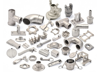
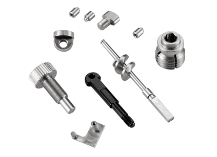
For companies like YETTA TECH Co., Ltd., mastering every detail of CNC machining is a core value. Since 2012, YETTA TECH has provided high-quality CNC machining parts to industries around the world—from aerospace and telecommunications to medical devices and energy systems. Their deep expertise and commitment to precision make them a trusted partner for both prototyping and full-scale production.


